
7 Way Round Pin Trailer Connector Wiring Diagram
Understanding the wiring diagram is essential for anyone looking to install a 7-pin trailer plug. Each pin represents a specific function, such as tail lights, brake lights, or turn signals. By following the wiring diagram, you can easily connect the corresponding wires from your vehicle's electrical system to the trailer plug.
7 Round Trailer Plug Wiring
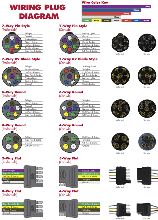
These diagrams will help ensure you wire your PJ Trailer using the correct standard for either a 4-way and 7-way plug wiring systems. 4-Way Plug Wiring 7-Way Plug Wiring Trailer plug connector diagrams for electrical towing connectors. View diagrams for our 4-way, 6-way & 7-way plugs.
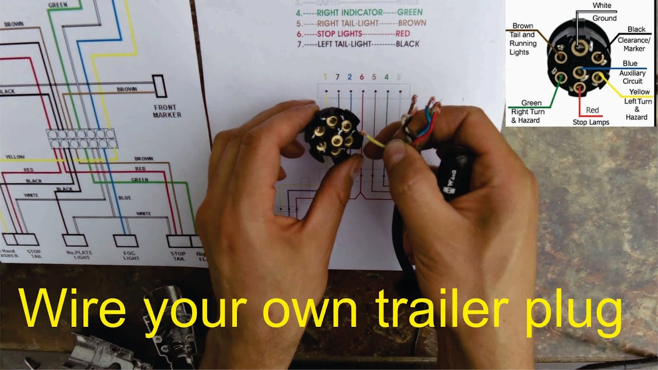
How to wire a trailer plug 7 pin (diagrams shown) YouTube
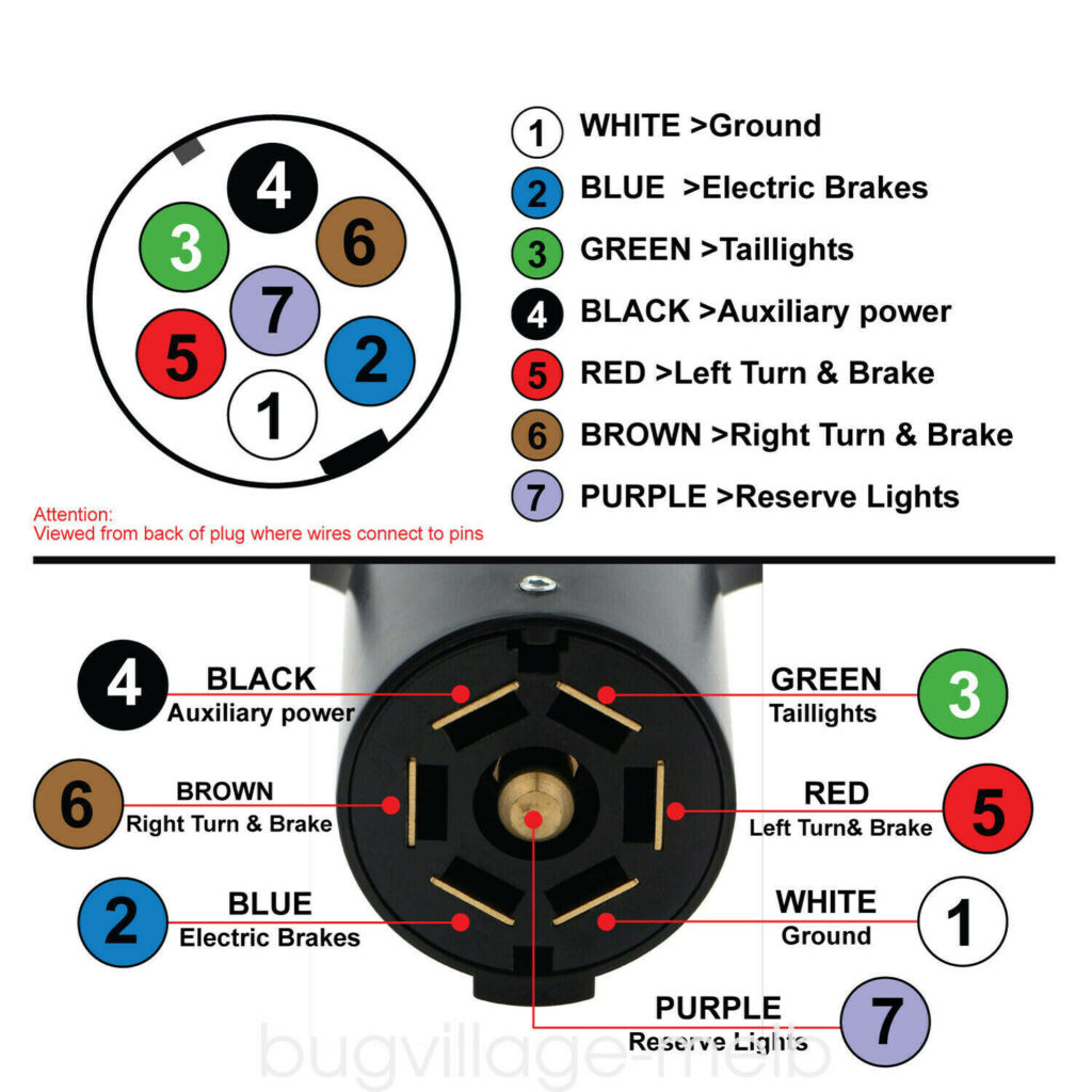
A 7 pin trailer wiring diagram is a schematic that shows the pinout and function of each wire in a 7-way round trailer connector. The standard 7-pin connector contains the following wires and functions: The diagram uses color coding and labeling to identify the purpose of each pin's wire. It traces the path of the wires from the connector.

7 Way Trailer Plug Wiring Instructions
In today's video The TrailerSmith replaces an old trailer plug with a Pollack 7 Way trailer plug and walks you through step-by-step how to do it for yourself.

Wiring Diagram 7 Way Trailer Plug
The minimum suggested wire size for a 7-way trailer plug is 16 gauge for the turn signals, brake lights, reverse lights, and running light wires. The suggested minimum for the ground, brake power, and battery hot lead wires is 12 gauge. Shop Custom Wiring Wiring a Trailer with a 7-Way: Step by Step
Trailer Plug Diagram 7 Way
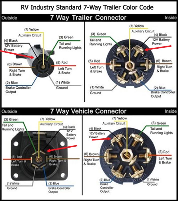
7-Way Wiring diagram for RV trailer plug. When wiring an RV trailer connector, it is best to wire by color function, as wire colors can vary. Here is a 7 Way Wiring diagram for the RV trailer plug hope this will help you. If you are looking at the inside of the trailer connector where the wires mount to the terminals starting at the top and.
7 Way Trailer Connector Wiring
How to Wire 7‐Way Trailer Plug for Power Jack Tools: Phillips head Screwdriver or Screw Gun Flat blade screw Wire Stripper Cutter Loosen screw on side to get the end of the7‐way off. Remove the white sleeve that holds the connector in place. Slide cover over 7‐way wire sheathing. Cut sheathing off to expose the 7 wires.
7 Way Trailer Plug Wiring Colors
7-Way RV Trailer Connector Wiring Diagram Question: trailer connector wireing diagram. need to know which color wire go to which post. asked by: Joann Expert Reply: When wiring a trailer connector, it is best to wire by function, as wire colors can vary.

Wiring Diagram For 7 Blade Trailer Plug 7 Way Rv Trailer Connector
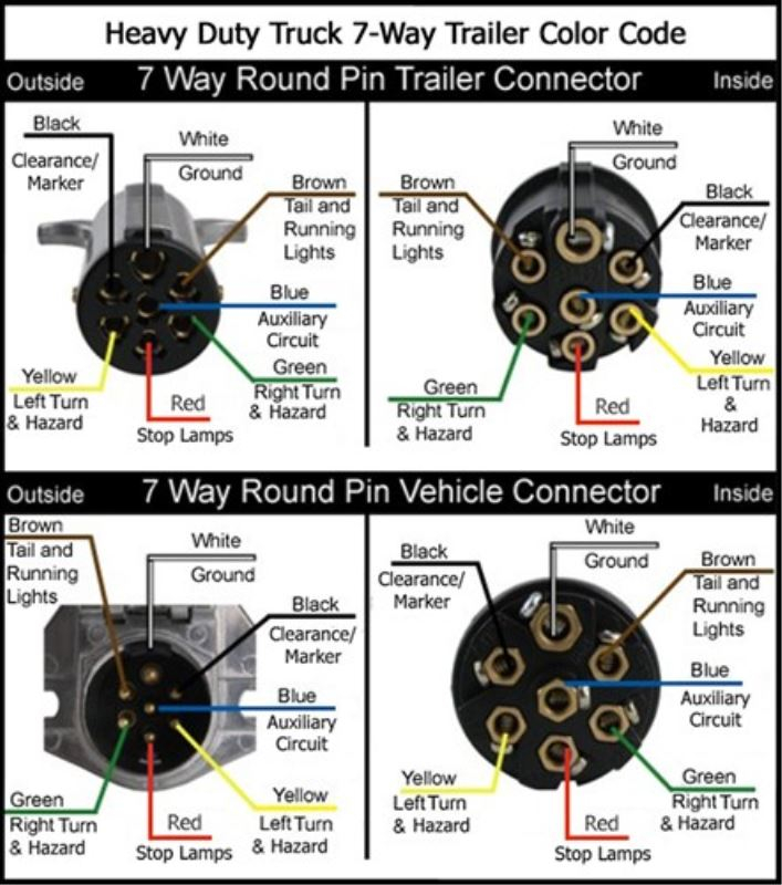
Wiring Diagram for 7-Way Round Pin Trailer and Vehicle Side Connectors Question: wiring pollak j560jun93 to 7pin round narva truck to trailer thank. asked by: Michael Expert Reply: I have added a photo detailing the wiring connections for the Pollack Heavy-Duty, 7-Pole, Round Pin conncetor, # PK11700, see link.
Wiring Configuration For 7Way Vehicle And Trailer Connectors
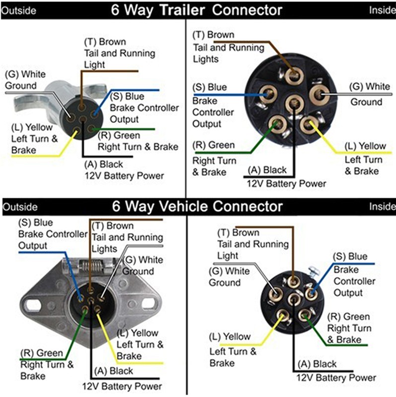
Use a circuit tester to verify connections. *NOTE: The fifth connection is sometimes used on 5-ways to power a reverse lockout on trailers with surge brakes. When this is the case, the lockout should be connected to the backup light circuit of the tow vehicle.

Heavy Duty 7 Way Trailer Plug Diagram Electrical Wiring
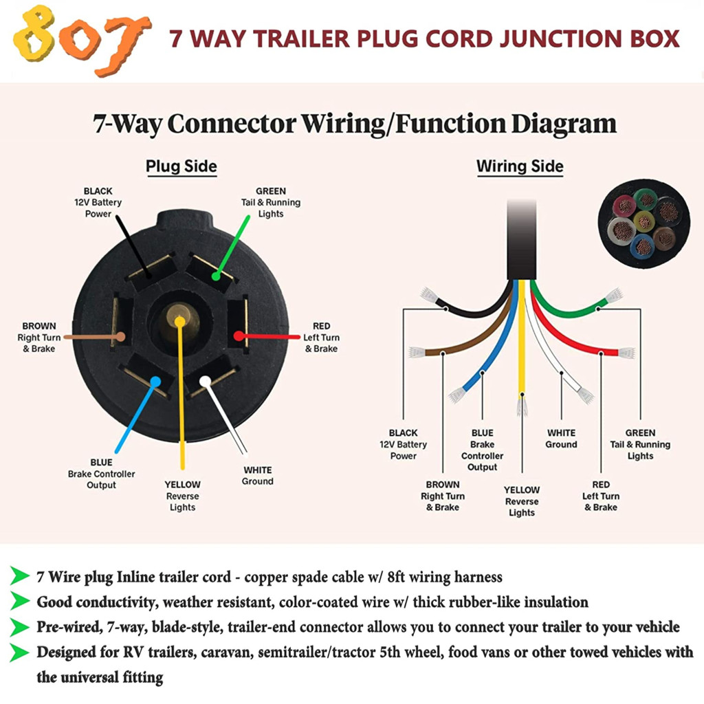
7-Way Trailer connecTor Wiring diagraM 7-Way Molded Trailer connecTor & cable BLACK BROWN GREEN YELLOW BLUE WHITE RED TRAILER END As viewed from front face of 7-way connector with molded on cable. 7-Way Wire color Wire color & gauge White / 10 gauge Blue / 12 gauge Green / 14 gauge Black / 10 gauge Red / 14 gauge Brown / 14 gauge Yellow / 14 gauge
7 Way Trailer Plug Wiring Diagram Wiring Diagram
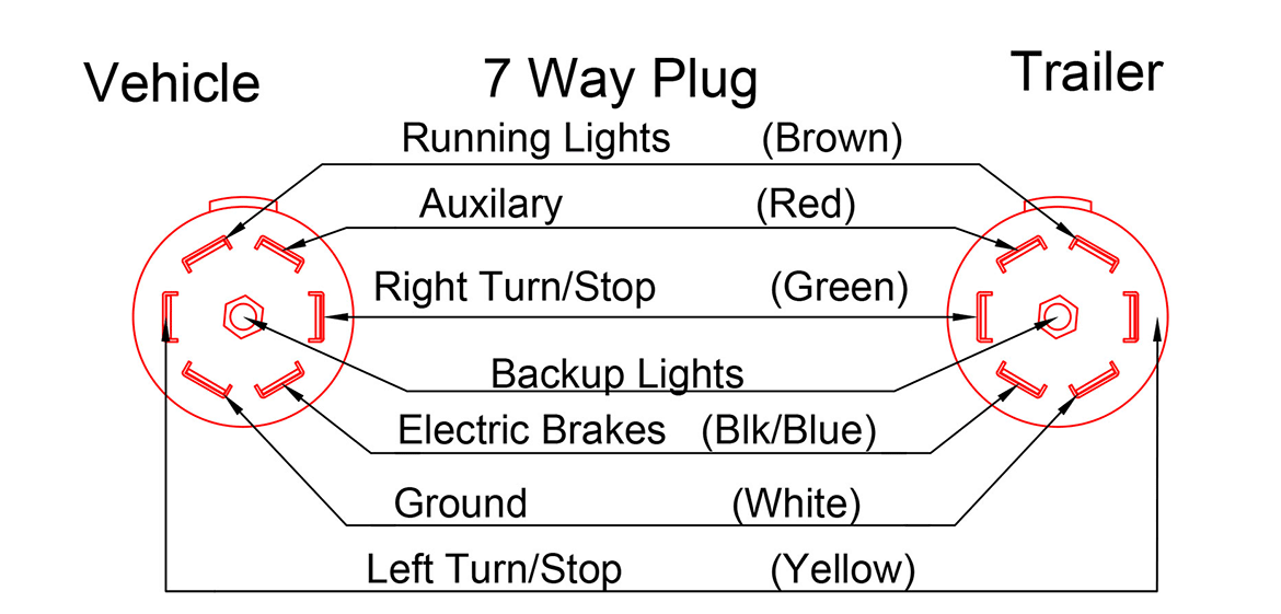
7 Way Plug Wiring Diagram Standard Wiring* This is the most common (Standard) wiring scheme for RV Plugs and the one used by major auto manufacturers today. * Always test wires for function and wire accordingly. This wiring scheme is for reference only. copyright © 2001, Country Trailer Sales All Rights Reserved

7 Plug Trailer Wiring Diagram Diagrams 7way Wiring Diagram Library
Clamp. Slide Plug Body back onto Trailer Wiring, exposing terminals Turn Turn on back of Plug Face Auxiliary. Wiring schematics above are looking at the REAR of the plug (not used) face, with the Setscrew at the 12 o'clock position Ground Brakes. Secure wiring in terminal clamps, ensuring that wires do. NOT touch multiple terminals Face Notch.
7 Pin Trailer Connector Wiring Diagrams
Hooking up a seven-way trailer wiring diagram is a great way to make sure that your vehicle or trailer is equipped with the necessary lights, brakes, and other important system components.

7way Trailer Plug Wiring Diagram
Chapter 7 Equipping Your Vehicle with Proper Trailer Wiring Any vehicle towing a trailer requires a trailer wiring harness to safely connect the taillights, turn signals, brake lights and other necessary electrical systems.

Wiring 7 Prong Trailer Plug 7 Way Trailer Plug Wiring Diagram Ford
The 7-Way Trailer Plug is around 2″ diameter connector that allows an additional pin for an auxiliary 12-volt power or backup lights. It is usually used for towing heavy-duty cargo trailers, aluminum trailers, dump trailers, utility / landscape trailers, equipment trailers, open car haulers and enclosed car haulers.